
First revision of schematics complete
To make sure as many people as possible can buy the T-Time, I need to design it so I don't have to hand-assemble all of them. What better way to do this than making some schematics? :)
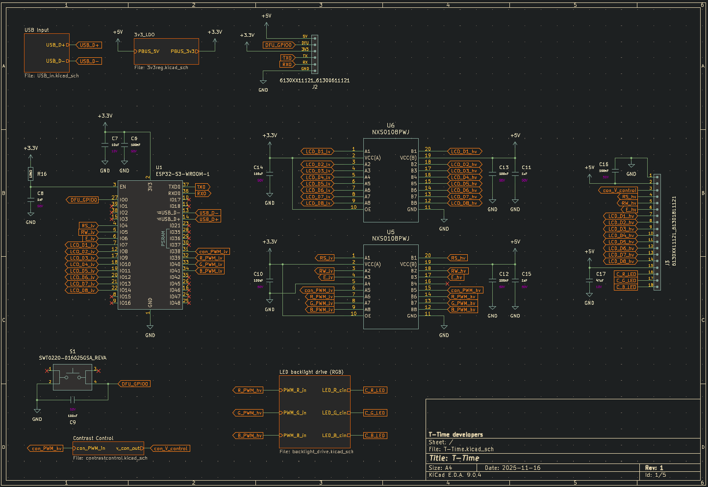
Using the ESP32-S3 devkitC reference schematic, I started to lay out the essential components for the ESP32 to function. Most importantly, it needs USB connection for power and programming, as well as input protection and voltage regulation to run the 3.3V rail from USB standard 5V output.
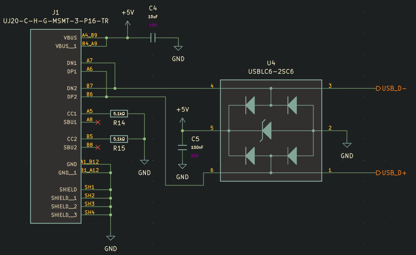
The USB-C input is relatively simple. There's a couple decoupling caps for the 5V rail, and some 5.1k resistors to ground on CC1 and CC2 to tell whatever USB power supply is connected to output just 5V. For the data lines, it's essential to prevent surges or over-voltage by using high speed TVS diodes. I found a nice chip, the USBLC6-2SC6 from ST Microelectronics that combines 5V surge and D+/D- surge protection into one single chip. It's meant for USB, and has very low parasitic capacitance to prevent issues with USB data interference.
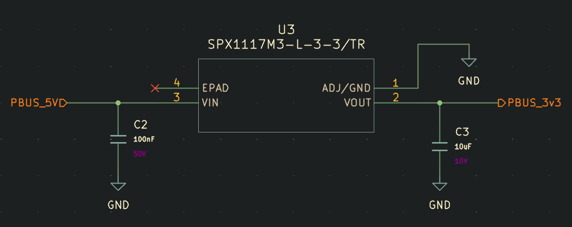
Next, we've got the 3.3V LDO for powering the ESP32. This circuit is dead simple, and is just a single 3.3V fixed output 1117 linear regulator IC plus some necessary decoupling caps.
Finally, we arrive at the ESP32 with fresh 3.3V power and safe USB data lines. From here, a ton of connections branch out to peripheral hardware. I've made the choice to stick with 8-bit parallel connections to the LCD, since you can get smoother animations and faster custom character swaps.
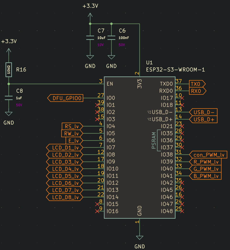
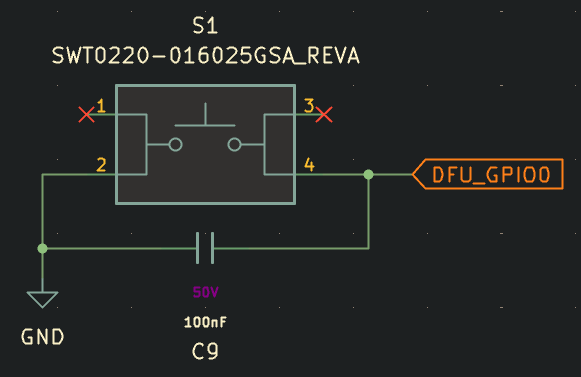
Just like on the devkit boards, I've added a small tactile button which will be accessible through a small hole on the case, either to put the ESP32 into DFU mode on boot, or after boot to reset the WIFI information in case you need to reconnect it to a new network without loading the web portal.
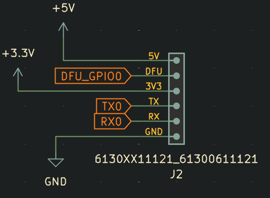
For programming or debugging simplicity, I've also added a small unpopulated header on the board to access the power rails, serial pins, and GPIO0 DFU pin.
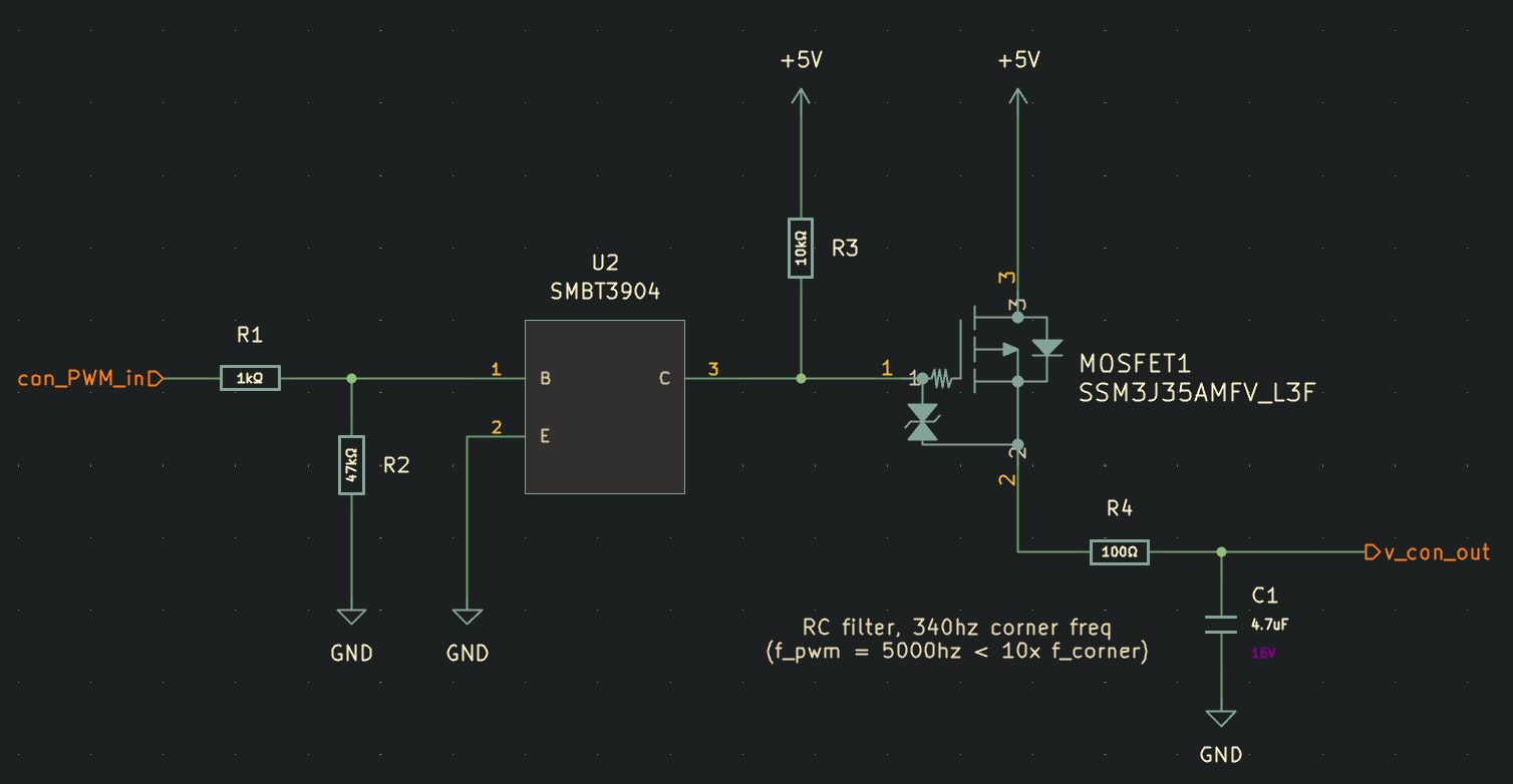
Moving back to the LCD, I don't like how many boards, including the ones I used in my T-Time MinuTe prototypes require the user to pre-set contrast with a potentiometer. If I ship these to people out in Boston from where I am, there's a good chance the contrast won't look the way it's intended to. Also temperature and age of the components will eventually cause the contrast set point to look "off", either washed out or oversaturated. I want end users to be able to control the contrast digitally from the web server that's hosted on the ESP32, so I designed this simple circuit to drive a 0-5V high side signal. First a 5khz PWM signal from the ESP32 passes through a NPN transistor. This BJT transistor is responsible for isolating the 3.3V ESP32 GPIO pin from the 5V high side P-channel MOSFET gate control circuit. It also serves to invert the signal from our ESP32, since the gate of the P-Channel MOSFET must be at 5V (pulled up, BJT collector floating) for it to be off, and will pull the gate of the MOSFET low when our PWM signal goes high, acting as a simple gate driver. When the output PWM Signal passes through the MOSFET, it reaches a RC filter with the corner frequency set around 340 hz, over 10x lower than the switching frequency, which should produce a fairly stable output voltage that is adjustable between 0-5V. The LCD contrast pin draws 1-2mA max, so this resistance should be small enough to still provide the necessary current without a significant voltage drop.
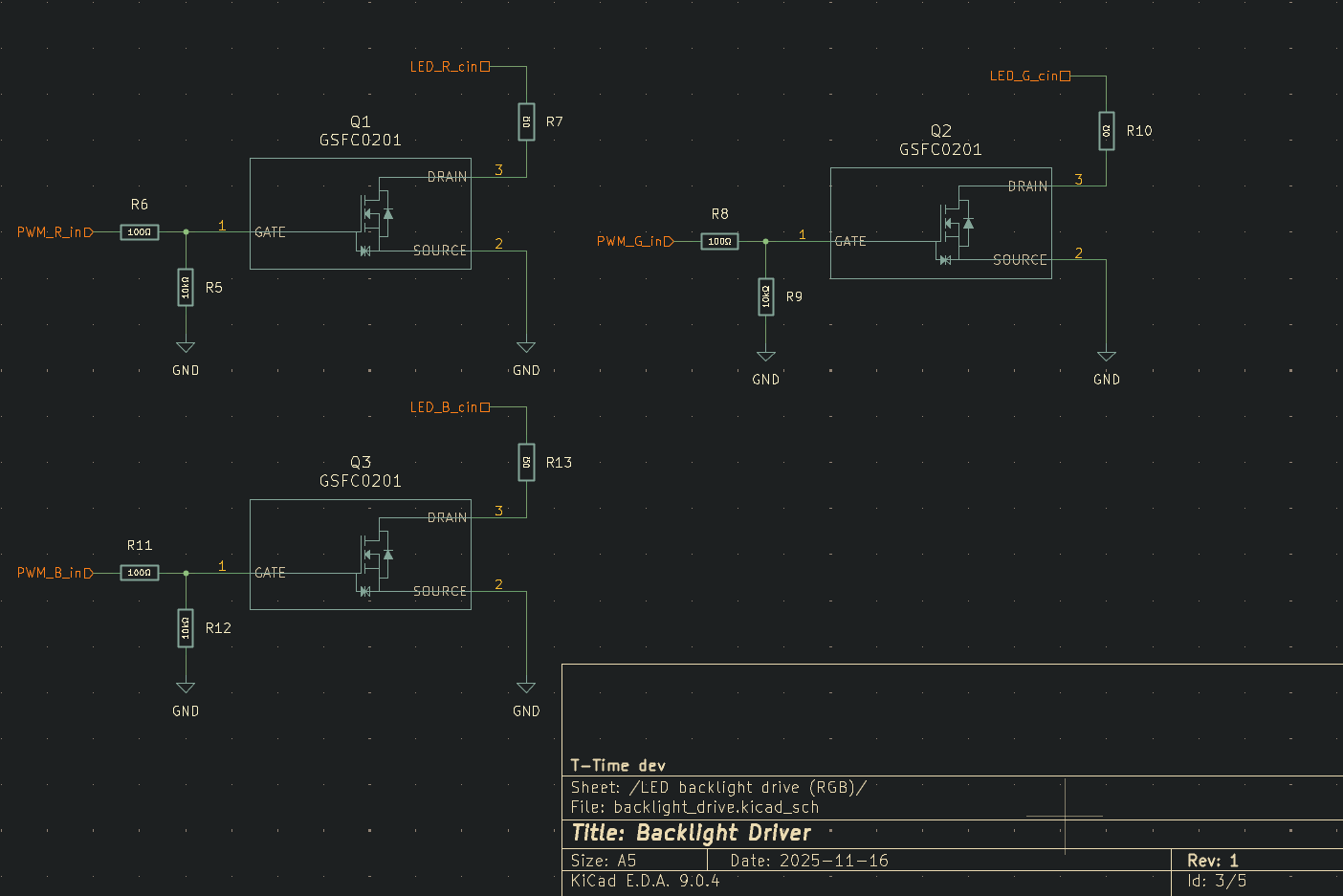
Backlight control is also essential, whether to turn the backlight off at night, adjust the brightness, or in the case of some models equipped with RGB backlights, control their color. Using 3 800mA N-channel logic level MOSFETS, I designed these super simple circuits with an optional spot for a current limiting resistor in case the LCD doesn't have one. By default, these are populated with 0 ohm resistors.
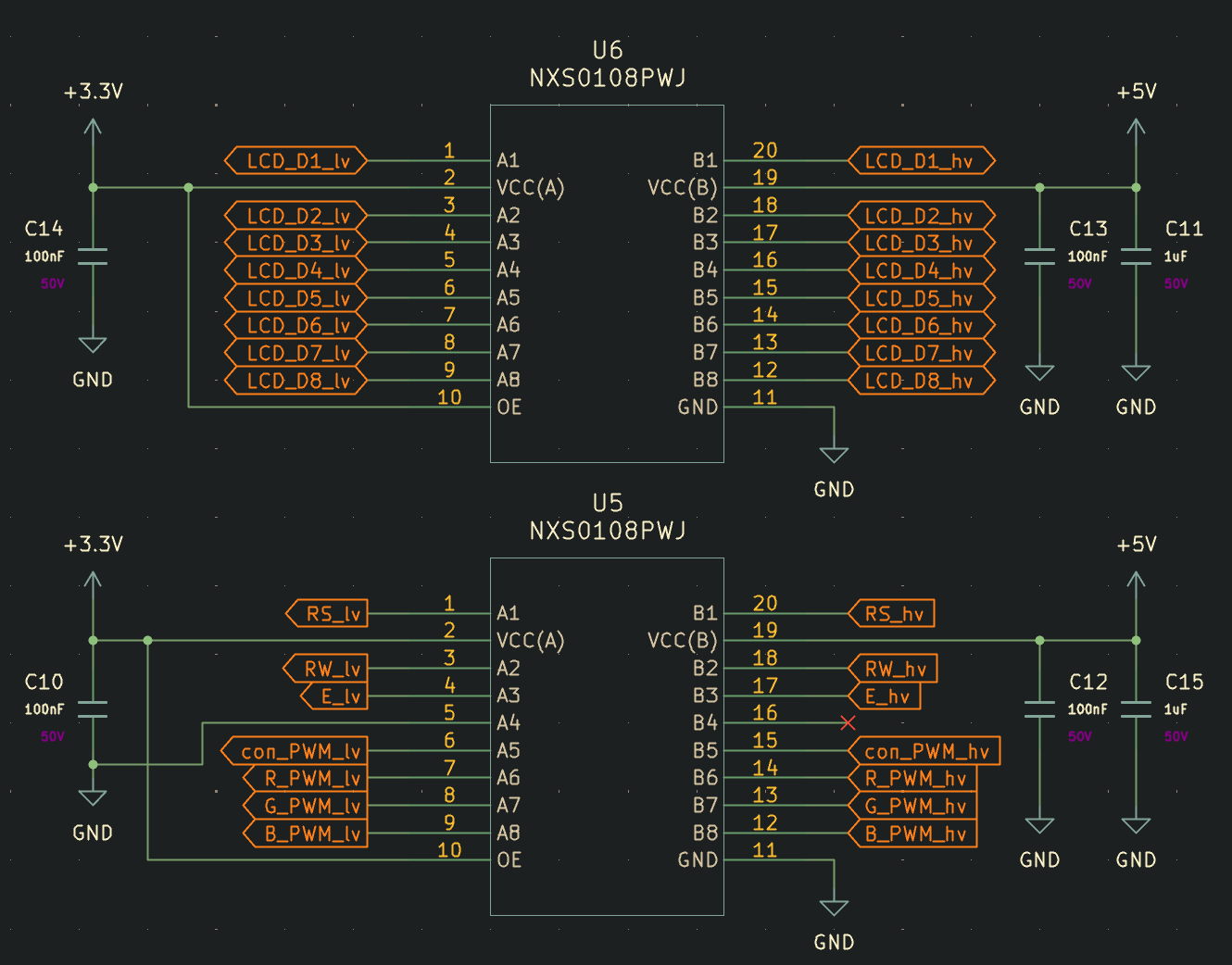
Unfortunately a necessary evil in this design are two large logic level converter chips. These are used to step the ESP32's 3.3V logic level signals up to 5V logic level signals for driving the LCD data lines, control pins, PWM, and contrast circuit. Most character LCDs available that have form factors that work well for this project are 5V logic level rated, and unfortunately the digital pins are all bidirectional, so it necessitates having proper logic level converters.
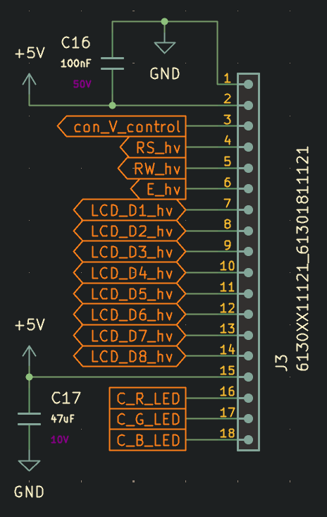
Finally, we reach the large output connector to the LCD which is wired in the standard format for most character LCDs, plus two extra pins for colored backlights. I've also included a large decoupling cap for the backlights, since I don't want users to experience backlight flickering if the ESP draws a bunch of power to get data over WIFI, which is something I noticed occurring on the prototype models.
Overall, I'm happy with the progress towards making a more robust electrical system for the T-Time, and I'm looking forward to starting PCB layout soon when I have another gap in assignments this semester :)
0 Comments Add a Comment?